If you’ve downloaded a DioGrid panel STL and loaded it into your slicer, you may have noticed the suggested orientation looks wrong: the panel is flat on the bed, face-side down, looking like it’s going to print into the surface.
It’s not wrong. It’s intentional — and it makes a meaningful visual difference.
The problem with upright printing
Most wall-like objects print standing up. It’s the intuitive orientation and it minimizes support material. But for display models, upright printing creates a problem:
Layer lines run horizontally across the most visible surface.
For a wall panel, the “viewer-facing” side is what people see when they look into the diorama. Printed upright, every layer change produces a visible ridge across that surface — even at 0.1 mm layer heights. You can sand it, but that removes panel detail.
Face-down: the FDM trick
When you flip the panel face-down, the display surface is now the first layer — pressed firmly against the bed.
FDM printers squish that first layer slightly, which actually fills fine surface detail instead of stacking ridges across it. The result:
- No horizontal layer lines on the viewer-facing face
- Panel engraving, bolt detail, and conduit grooves print crisply
- The back side (which faces into the wall) has normal layer lines — but no one sees that
The tradeoff is that the back face now has a slight “elephant foot” from first-layer squish. For modular systems like DioGrid, the back is a tongue-and-groove rail joint, so the elephant foot is removed by the mating geometry anyway.
Slicer settings that matter
If you’re printing DioGrid panels, these settings complement the face-down orientation:
| Setting | Recommended |
|---|---|
| Layer height | 0.15–0.2 mm |
| First layer height | 0.25 mm |
| First layer speed | 25–35 mm/s |
| Supports | None required for standard panels |
| Build plate adhesion | Brim (3–5 lines) |
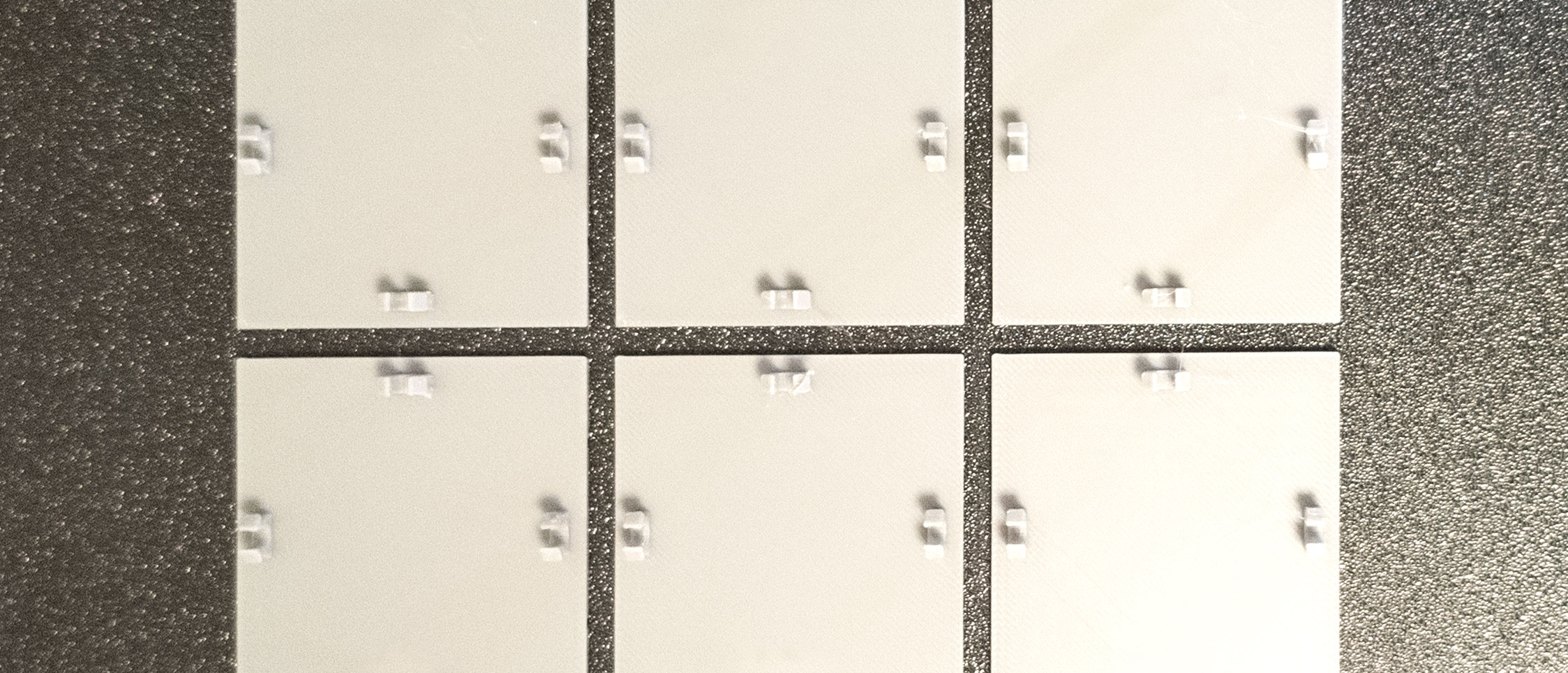
Bambu Lab printers with textured PEI plates produce the best face-down surfaces in our tests — the texture adds grip during printing and the surface detail on the panel reads as intentional matte finish.
How DioGrid communicates this
The export panel in the app (RightPanel → “Download STLs”) ships panels pre-oriented. If you export to 3MF, the orientation data is embedded and your slicer should load it correctly without manual adjustment.
STL exports don’t include orientation metadata — it’s a format limitation. For those, orient the part so the engraved face points toward the build plate.
Does this apply to floor tiles?
No — floor tiles print flat and face-up. The top surface of a floor tile picks up texture from the textured build plate (roughness, grid lines), which looks intentional for a worn sci-fi floor. You want those layer characteristics.
The face-down rule applies specifically to vertical display panels: walls, doors, and connector strips.
Have a question about print settings or panel orientation? Open the app and use the Help panel — we’re adding a print-settings guide there as well.